Категории
Новые продукты
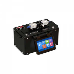
LDC-100 скалыватель оптических волокон большого диаметра * Применимо к волокнам диаметром 80~600 мкм *Вакуумный насос с V-образной канавкой удобно класть волокно *Прочное лезвие, срок службы более 20000 раз *Хранение данных 4000 групп * Удобное графическое меню, простое в эксплуатации Больше
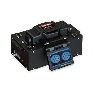
S-22 Многожильный сварочный аппарат для оптоволокна Первый полностью автоматический многоядерный сварочный аппарат F iber Fusion в Китае _ _ _ Больше
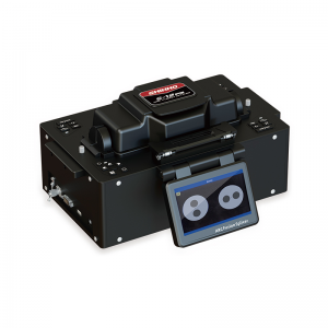
Поляризация поддерживая (PM) в волокна splicer сплавливания с-12 * Ядра к ядру согласование, низкие потери сплайсинга * Наблюдение Endview и профиль и выравнивание * Автоматическая калибровка дуги и сплайсинга * ПМ волокна 45 и 90 градусов регулировка Больше
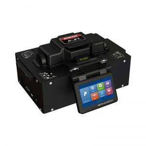
S-37 LDF Специальный сварочный аппарат для сварки волокон SHINHO S-37 — это последняя модель, которую мы разработали, она может сращивать оптические волокна диаметром от 125 до 400 мкм с низкими потерями при сращивании. Мы оснастили машину 3 различными держателями волокна и 2 парами запасных электродов. Больше
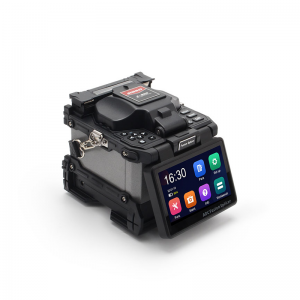
сердечник для выравнивания волокон сращиватель x900 сварочный аппарат с шестью двигателями, настоящая технология центровки сердечника. Сплайсинг 6 с, нагрев 16 с, автоматическое определение типов волокон. используется для wan / man / телекоммуникационных проектов. Больше
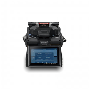
Надежный многофункциональный дуговой сварочный аппарат S16 Прочный промышленный дизайн, противоударный, пыленепроницаемый и водонепроницаемый. многофункциональный держатель для оголенного волокна, патч-кордов, кабеля и т. д. быстрое соединение и нагрев, автоматическая калибровка дуги. Больше
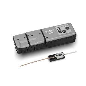
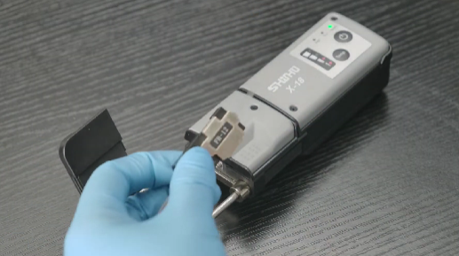
Термостриппер SHINHO X-18 для ленточных волокон Термостриппер Shinho X-18 — это недавно разработанный ручной термостриппер, специально разработанный для неразрушающего термозачистки оболочки ленточного кабеля до 12 волокон. Хороший и надежный инструмент для сращивания ленточных волокон. Больше
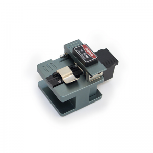
Высокоточный скалыватель оптических волокон X-50D Небольшой размер и легкий вес, прост в эксплуатации. Высокая точность и стабильная работа. Срок службы лезвия более 48000 раз, длина скола волокна 5 ~ 20 мм. Материал высокого качества Больше
Ribbon Fiber Splicing Best Practices: How to Achieve Fast, Reliable, and Low-Loss Fusion Results
With the rapid development of 5G, data centers, and FTTH networks, ribbon fiber has become increasingly popular in backbone and metropolitan area networks due to its high density and improved construction efficiency. Compared with traditional single-fiber splicing, ribbon fiber allows multiple fibers (typically 4, 8, 12, or more) to be spliced simultaneously, greatly increasing productivity. However, it also requires higher precision and stricter operational control.
Ribbon fiber arranges multiple optical fibers side by side in a flat ribbon structure, usually with a pitch of 200 μm or 250 μm. Splicing is performed with a dedicated ribbon fusion splicer that uses V-grooves to hold and align multiple fibers for simultaneous fusion.
A representative example is the Shinho X950 fusion splicer, which supports splicing of 2–16 fibers and is supplied with a thermal stripper, cleaver, and other preparation tools. Its low splice loss makes it a dependable option for high-density optical network construction.
The main advantages of ribbon fiber splicing include significantly faster splicing through simultaneous multi-fiber processing, low average splice loss (typically below 0.1 dB per fiber), and suitability for high-density cable deployment. At the same time, inadequate preparation or incorrect operation can result in inconsistent loss among fibers, end-face contamination, or fiber breakage.
Preparation is the most critical stage because it directly affects the splice success rate.
Choose a clean, wind-free, dust-free environment with relative humidity below 70%, such as an indoor workspace or dedicated splicing tent. Dust and airflow can easily contaminate fiber end-faces and lead to splicing failures. Keep the workstation organized and have alcohol, lint-free wipes, and cleaning brushes ready before starting.
Prepare a ribbon fusion splicer with the appropriate ribbon holders or clamps, a thermal stripper to minimize mechanical damage during coating removal, a ribbon-specific precision cleaver, properly sized heat-shrink sleeves, high-purity isopropyl alcohol (99% or higher), fiber cleaning solution, and testing instruments such as an optical power meter or OTDR.
Expose roughly one meter of ribbon fiber from the cable by removing loose tubes and filling compounds. Use the thermal stripper to remove the coating uniformly, typically over a length of 30–40 mm. Clean the fibers thoroughly with alcohol until all coating residue, dust, and oil are removed. Because the fibers are connected in a ribbon structure, contamination on a single fiber can affect the entire ribbon. Finally, use a fiber arranging tool to ensure consistent spacing between fibers and to eliminate twisting or crossing.
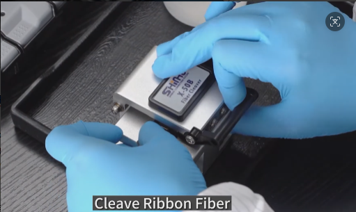
The fiber end-face must be flat, perpendicular, and free from cracks, burrs, or lip defects. A ribbon-specific cleaver should be used to cleave all fibers simultaneously, producing consistent bare fiber lengths of approximately 10–15 mm. After cleaving, place the fibers into the splicer immediately to avoid secondary contamination.
Select the correct V-groove according to the ribbon pitch (200 μm or 250 μm). Insert the ribbon so that it lies flat and is not reversed. Modern fusion splicers, including models such as the Shinho X950, generally provide automatic alignment, but operators should still verify alignment visually through the microscope. Close the clamps gently to avoid crushing the fibers.
Adjust parameters such as pre-arc current, splice current, and feed amount according to the fiber type (for example, G.652 or G.657) and the ambient temperature. Many advanced splicers include intelligent optimization features, but following the manufacturer's preset recommendations is advisable during initial operation. During fusion, observe the splice image to confirm that the splice point appears round, symmetrical, and free from bubbles or deformation.
Immediately position the heat-shrink sleeve over the splice and place it in the heater. Some splicers provide dual heaters to improve efficiency. Allow the sleeve to cool naturally after heating and verify that it has shrunk evenly, contains no bubbles, and provides secure mechanical protection.
Follow the standard fiber color code sequence carefully to avoid misconnection. Apply clear labels or color identification after splicing to simplify future maintenance and troubleshooting.
High splice loss is often caused by contaminated end-faces, poor cleaving, alignment errors, or incorrect splice parameters. The recommended corrective action is to clean, recleave, and re-splice the fibers. Fiber breakage commonly results from stripping damage, excessively small bending radii, or excessive clamp pressure. Inconsistent loss across multiple fibers is usually associated with pitch mismatch or uneven fiber arrangement; pitch-conversion holders can help address this issue. Equipment alarms may indicate contamination in the V-grooves, on the electrodes, or on the lenses, so regular cleaning and monitoring of blade and electrode life are essential. After each ribbon splice, perform bidirectional OTDR testing and re-splice any fiber whose loss exceeds 0.3 dB.
Daily maintenance should include cleaning the V-grooves, electrodes, and observation lenses, as well as replacing consumable parts at the recommended intervals.
Successful ribbon fiber splicing depends on four fundamentals: cleaning, cleaving, alignment, and protection. By following standardized procedures and maintaining proper equipment, technicians can achieve efficient, low-loss splicing that improves network performance and reduces long-term maintenance costs. In practical projects, targeted practice with the specific fusion splicer model and fiber type being used, along with careful reference to the manufacturer's technical documentation, will help ensure consistent, high-quality results.


Приглашаем вас зарегистрировать новостную рассылку, если у вас есть интерес к нашим продуктам, мы будем держать вас в курсе наших новостей, информации о продуктах и рекламных акциях, если таковые имеются.
© Авторское право: SHINHO OPTICS LIMITED Все права защищены.


 русский
 English
 français
 italiano
 español
 português
 العربية
 ไทย
ไทย हिन्दी
 Indonesia
 中文
中文